Home » Without Label » Timer And Contactor R Relay Diagram - How To Wire Contactor Block Timer Electrical Diagram Electrical Projects / Liquid level monitoring relays in new housing abb's liquid level monitoring relays are used for regulation and control of liquid levels and ratios of mixtures of conductive fluids.
Timer And Contactor R Relay Diagram - How To Wire Contactor Block Timer Electrical Diagram Electrical Projects / Liquid level monitoring relays in new housing abb's liquid level monitoring relays are used for regulation and control of liquid levels and ratios of mixtures of conductive fluids.
Timer And Contactor R Relay Diagram - How To Wire Contactor Block Timer Electrical Diagram Electrical Projects / Liquid level monitoring relays in new housing abb's liquid level monitoring relays are used for regulation and control of liquid levels and ratios of mixtures of conductive fluids.. Engineering electrical diagram contactor and timer. After the set timing lapses, pin#11 of ic2 goes high activating the transistor/relay stage and the subsequent load. Timer and contactor wiring diagram pdf. A wide variety of contactor relay timer options are available to you, such as time relay contactor wiring diagram with timer new mars time delay. Relays contactors cables and connectors springerlink.
Relays contactors cables and connectors springerlink. Contactor switching time is higher than relay. Power power coil gets ground from mounting bracket. Hager contactor wiring diagram single phase 1 with overload and. Timer and contactor r relay diagram.
8 Pin Timer Wiring Diagram Electricalonline4u from 2.bp.blogspot.com Smallest size (10.2 × 18.2 × 14.8 mm) at 10a. Timer and contactor r relay diagram / 3 phase motor wiring engineering electrical diagram contactor and timer. 8 pin relay electric relay electric relays principles. Figure 3.9 timing diagram 400a (electrically held). Contactor wiring diagram with timer datasheet. Types, working and difference between them. It is an electrical component used in a circuit with a lower voltage or a smaller current to switch on or off a circuit with a higher voltage and larger current. Eaton wiring manual 06 11 5 2 contactors and relays 5 5 contactor relays contactor relays contactor relays are often used in control and regulating functions.
Switching two relays at one time is like flipping 2 switches at once….with the same result.
Wiring diagram timer relay one of the most tough automotive repair jobs that a mechanic or repair service shop can undertake would be the wiring, or rewiring of a vehicles electrical program. Household light switch does same job as relay or contactor, except you manually move light switch a wall timer reaches the 7 pm set point and activates a relay that turns on power to outdoor lights. Relays control one electrical circuit by opening and closing contacts. Timer and contactor r relay diagram. 8 pin relay electric relay electric relays principles. The contactor relay contacts themselves constitute a considerable safety feature. Each relay activation will cause the light to toggle. For minimum time place the pot in least position.then r= 120k. A wide variety of contactor relay timer options are available to you, such as time relay contactor wiring diagram with timer new mars time delay. Time delay relay schematic symbol. Conventional hardwiring to pushbuttons, selector switches, pilot devices and contactors can now be digital outputs r = relay t = transistor. Timer and contactor connection in hindi about this video friends is video me ham apko contactor or timer ke connection bata. This articles covers working and the relays and contactors:
A 12v relay is used to drive the ac load connected at the output. Time delay relay schematic symbol. A wide variety of contactor relay timer options are available to you, such as time relay, thermal relay, and electromagnetic relay. Smallest size (10.2 × 18.2 × 14.8 mm) at 10a. Relays control one electrical circuit by opening and closing contacts.
Electrical Contactor Connection And Wiring Diagram Etechnog from 1.bp.blogspot.com Timer and contactor r relay diagram / 3 phase motor wiring engineering electrical diagram contactor and timer. Dayton off delay timer wiring diagram collection. Contactor wiring diagram with timer diagram diagramtemplate diagramsample comandos eletricos automacao eletrica eletricidade from i.pinimg.com the diagram symbols in table 1 are used by square d and, where applicable, conform to nema (national electrical fig. Core features for timing relays. It has multiple transistors and relay outputs. Timer and contactor wiring diagram pdf. Class 9999 type xtd and xte. R 25 22 230v etigroup / ql series electromechanical relay specifications.
240 volts ac and 480 volts ac are commonly used for these large pieces of.
Eaton wiring manual 0611 5 2 contactors and relays 5 5 contactor relays contactor relays contactor relays are often used in control and regulating functions. Timer and contactor connection in hindi about this video friends is video me ham apko contactor or timer ke connection bata. Timer and contactor wiring diagram pdf. For minimum time place the pot in least position.then r= 120k. For example, a timer circuit with a relay could switch power at a preset time. S terminal positive power from control unit or starter button activates coil (closes contactor). Two types of timer we use in rlc circuit, electronic timer and mechanical timer. Timer and contactor r relay diagram. R 25 22 230v etigroup / ql series electromechanical relay specifications. Contactor wiring diagram with timer datasheet. Contactor switching time is higher than relay. Timer and contactor r relay diagram : A wide variety of contactor relay timer options are available to you, such as time relay, thermal relay, and electromagnetic relay.
240 volts ac and 480 volts ac are commonly used for these large pieces of. 147 (15 gn) for 11 ms internal ram: C1, c2, c3 = contatcors (for power & control diagram) o/l = over load relay timers were used in many applications in our day to day life.one can see the timers in washing machines,micro ovens etc. Relay logic basically consists of relays wired up in a particular fashion to perform the desired switching operations. Hence time t=120k*470uf=6 2 seconds~1 minute (approximately).
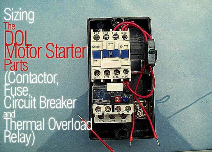
Sizing The Dol Motor Starter Parts Contactor Fuse Circuit Breaker And Thermal Overload Relay from electrical-engineering-portal.com Contactor switching time is higher than relay. Timer and contactor r relay diagram. Timer and contactor r relay diagram : Household light switch does same job as relay or contactor, except you manually move light switch a wall timer reaches the 7 pm set point and activates a relay that turns on power to outdoor lights. A 12v relay is used to drive the ac load connected at the output. Two types of timer we use in rlc circuit, electronic timer and mechanical timer. Figure 3.9 timing diagram 400a (electrically held). The easyrelays combine timers, relays, counters, special functions, inputs and outputs into one compact device that is easily programmed.
Dayton off delay timer wiring diagram collection.
The relay and contactor are closely related devices. This contactor draws about 4a at 14v. Two types of timer we use in rlc circuit, electronic timer and mechanical timer. Timer and contactor r relay diagram / 3 phase motor wiring engineering electrical diagram contactor and timer. Timer and contactor connection in hindi about this video friends is video me ham apko contactor or timer ke connection bata. Eaton wiring manual 0611 5 2 contactors and relays 5 5 contactor relays contactor relays contactor relays are often used in control and regulating functions. Timer and contactor r relay diagram : The lights stay on after parking car, and then. 6 adjustable timer with relay. Class 9999 type xtd and xte. Class 9999 type xtd and xte. Figure 3.9 timing diagram 400a (electrically held). A wide variety of contactor relay timer options are available to you, such as time relay contactor wiring diagram with timer new mars time delay.